Analog Outputs
Uses
Analog outputs can be used for
- d'Arsonval movements (meter movements, eg used in analog multimeters)
- dimmable Lamps
- speed controllers, eg for fans (avionics cooling comes to mind :)
- valves
- other actuators
- speakers (eg. used in CD players and MP3 players) and others
In connection with a modulation scheme, it can be used eg. to control air-core instruments (like those found on a car dashboard).
Ways to generate an analog voltage from a digital signal
- PWM, Pulse Width Modulation (this is the method discussed here and used by PHCC)
- R2R Ladder, basically a bunch of (precision) resistors connected together in a way that looks like a ladder. Built from Resistors of two values, R and 2R (ie twice the value of the first).
For more detals see the DAC section on allaboutcircuits.com
PWM generated analog voltages
In most cases, when Digital-to-Analog is required, PWM (pulse width modulation) can be used as the method to generate these voltages.
PWM is usually the cheapest and easiest method for this. However, PWM is still only 0 Volts or it is 5Volts (for TTL level logic). The key is to calculate the average voltage of the PWM pulse. Often there is a low pass filter between the PWM output pin and the analog out terminal. This low pass filter "smoothes" the signal so it looks more like a real analog voltage than a bunch of HIGH/LOW pulses.
Nowadays, PWM is used for many purposes, here are just a few:
- switched power supply
- speed control of several different kinds of motors, DC, AC, three-phase
- stepping motors: current limiting, speed control, and microstepping
- servo control
- battery charging
- brightness control for lamps and LEDs
- and others
Available or planned PHCC Analog Out Daughterboards
DOA_AnOut1
Features:
- 16 channels
- 8 bit resolution
- uses DOA protocol
- primarily for d'Arsonval type of instruments
- other light loads can also be controlled with the built-in transistor outputs, eg to control cooling fan speed or dimmable lamps.
- open collector outputs, max 45V (or more, depending on transistor)
- software controllable refresh rate (usually called "PWM period")
Schematic and Layout
Rev.0B
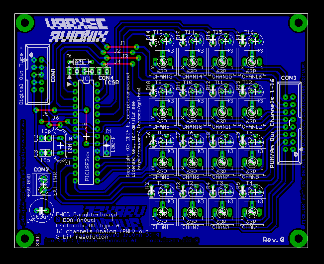 |
| Click to enlarge [46k, 651x531] |
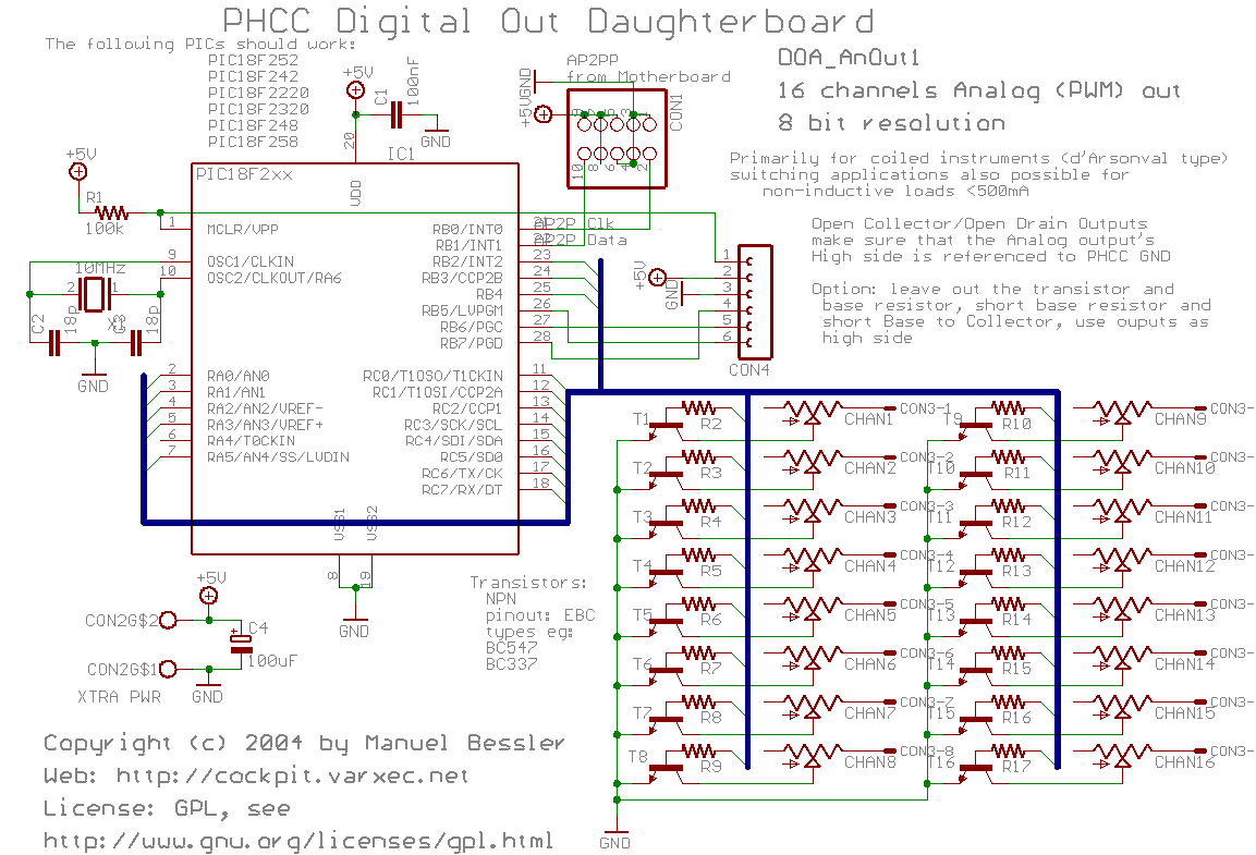 |
| Click to enlarge [45k, 1153x785] |
Rev.0C
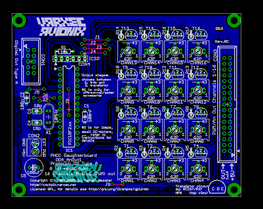 |
| Click to enlarge [70k, 903x718] |
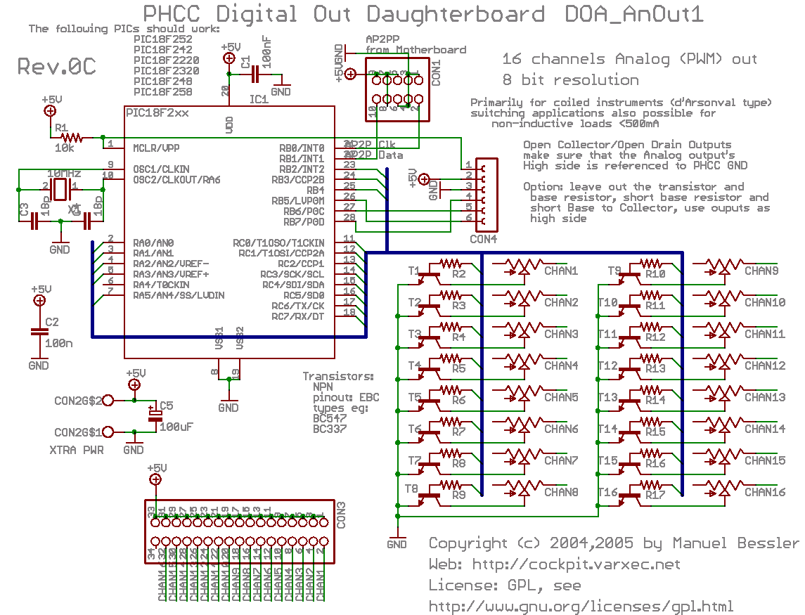 |
| Click to enlarge [51k, 1145x875] |
Assembly Instructions
Formats available:
- all in one big HTML page: AnOut1_assembly_tutorial.html
- PDF version: AnOut1_assembly_tutorial.pdf
Bill of Materials
see download page.
Eagle and Gerber files
see download page.
Changes between Revisions:
| Rev.0C | No functional changes. The outputs now feature a connector with more pins. The pinout on this connector thus changed. The odd-numbered pins all carry +5V, while the signals are on the even-numbered pins. Also added one capacitor, C2. Capacitor numbering changed as well. |
| Rev.0B | First public release. |
