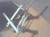
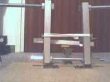
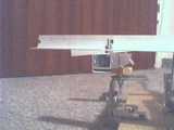
In this gallery you can see my new non-linked rudder pedal construction.
Basic materials were:
- threaded rods (M10 and M12)
- nuts
- a couple of angle brackets (I used 4)
- a particle board for the base
- some wood screws
- some aluminum profiles: L-shaped and square pipe
- some metal screws and nuts (I used M4)
- a 100k pot and two gear wheels for the transmission of the movement to pot angle
- a metal saw and a drill
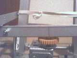
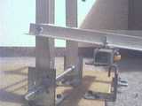
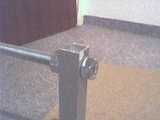
the white band is a rubber band as a very primitive centering mechanism.
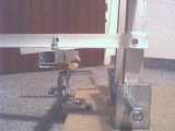
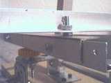
the vertical alu square pipes are both mounted on one axis and attached to the base board with the angle brackets.
right below the rubber band, an L-shaped alu profile is used to transmit movement to/from the crossbar (with the yellow gear wheel) where the pot goes (not installed in these pictures).
The two threaded rods mounted at the top of the square pipe are the rudder pedals (or where the pedals themselves will be mouted on). This is an M12 threaded rod.
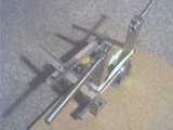
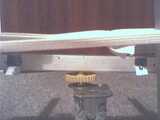
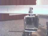
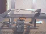
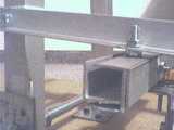
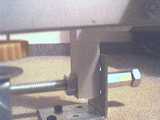
The crossbar with the yellow gear wheel. The pot will be mounted right next to it, through the angle backet.
Since the crossbar was built some months ago for some other part of the cockpit, it is not a 'clear design', I just used what I had.
It consists basically of two L-shaped alu profiles mounted together to form a U-shape.
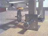
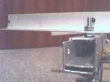
I added another L-shaped alu profile to it, which led to this setup where I had to cut out those two bent-out parts to reach the screws that hold the third L-shaped alu, as seen here.
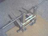
the crossbar is mounted on two connected L-shape brackets, screwed together.
This picture shows the L-shaped alu profiles that makes up the crossbar.
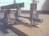
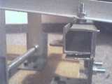
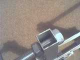
Here you can see how the pedal arms are connected to the crossbar to allow push/pull type operation.
The L-shape alu is attached to the pedal arms with a horizontal screw, and with a vertical screw to the crossbar.
The vertical screw in closeup
Here you see the 3 L-shaped alu profiles that make up the crossbar in detail
another angle
middle of the crossbar, with the axis where the gear is mounted. The hole to the left is for the pot
from the top.
the pedal base rod, where the pedal plate will be mounted on.
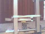
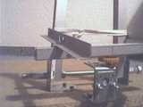
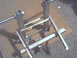
the rudder deflected in one direction.
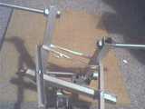
and deflected in the other direction, seen from another angle.