Assembling the PHCC Daughterboard "KEY64D_PH"
Intro
The Keymatrix Daughterboard "KEY64D_PH" is used to hook up
- switches
- push-buttons
- rotary selectors
- micro-switches
- and simliar
Both momentary and permanent action types of switches can be used. The software can then assign the actual meaning to those inputs.
You could even use a momentary switch to simulate a permanent action switch.
The inputs are arranged in a 8x8 matrix.
The PHCC motherboard can scan up to 16 of these boards.
How to connect stuff...
See docs.
Assembly
First start with the smaller components and work your way up to the bigger ones like sockets and connectors. This helps at places where the bigger stuff might get in the way of soldering smaller parts.
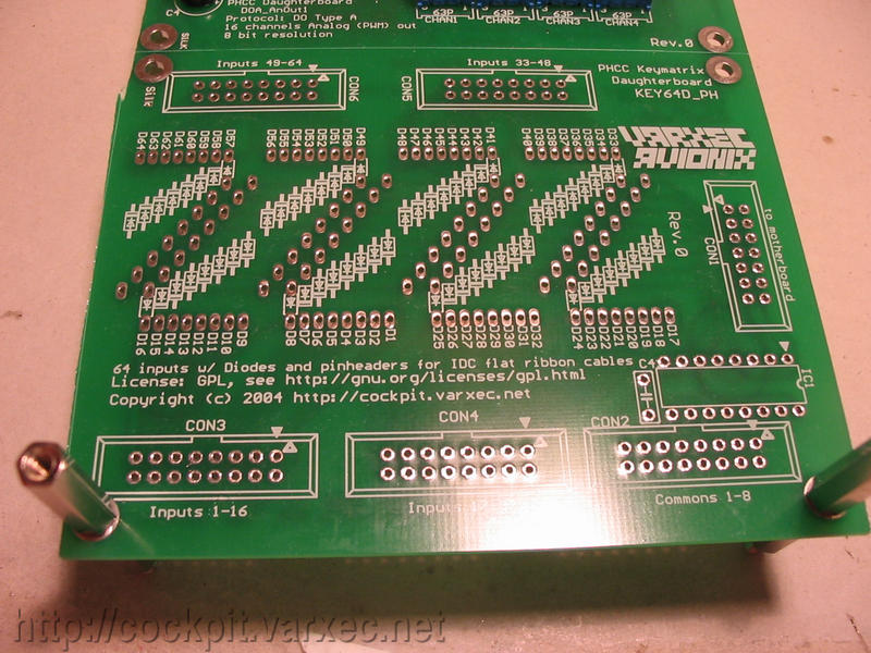 |
The bare board. This time, no jumper wires needed ;-) |
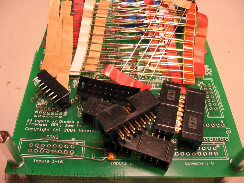 |
All the needed parts. |
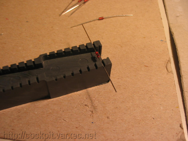 |
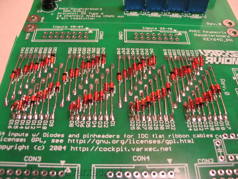
We start with the diodes. There are 64 of them needed. I used 1N4148. These should be cheap, just one or two cents each. Most types of diodes will work, just make sure that they fit. The package name is DO-34. Eight different lead spacings are used, so bend 8 groups of 8 diodes to the sizes needed for the board. |
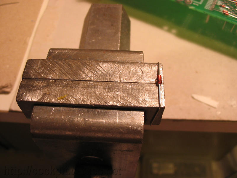 |
The bending tool used in the previous picture doesn't go all the way up to the widest and second-widest lead spacing, so I used my vice. |
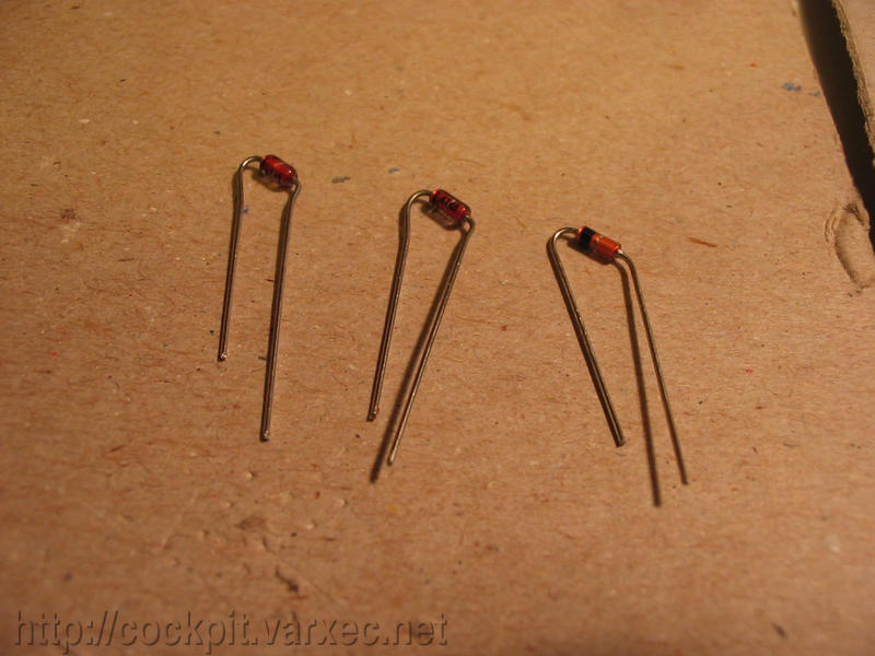 |
The shortest ones need to be bent similar to this for best fit and look. |
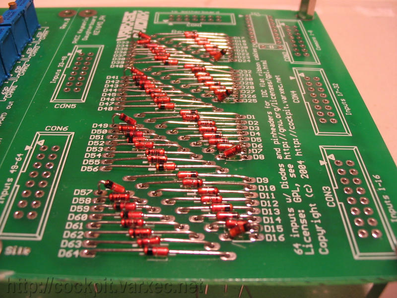 |
After all 64 diodes are bent and put in place, it is important to check that the polarity is correct. The cathode (usually marked with a ring) has to point outward, away from the board. Its easy to overlook a diode that sits the wrong way, so double check. What happens when you overlook diodes that are soldered in the wrong way ? Not much, its not critical. It might result in 'ghosting' of inputs. Check docs for details. |
 |
Now we are ready to solder them in. You could do it one-by-one, but I prefer to do them in bigger sets. |
 |
So I tried a new method to hold all diodes in place until they are soldered. The pin-bending method just makes it harder to get to the solder pads, so... |
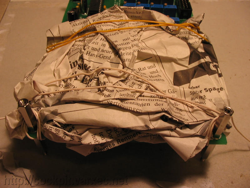 |
... I came up with this: newspaper, folded and wrinkled up like the picture shows. |
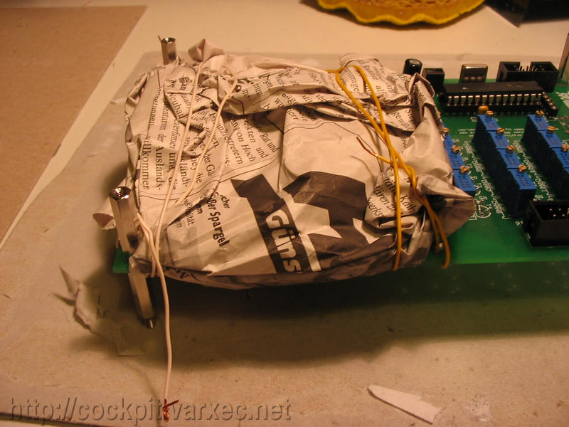 |
Using cable to hold it in place. |
 |
It indeed works :) |
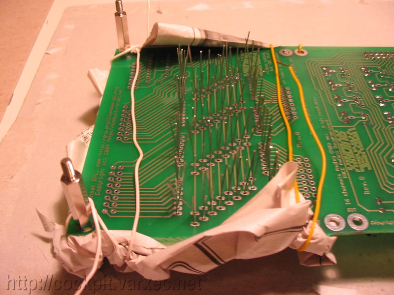 |
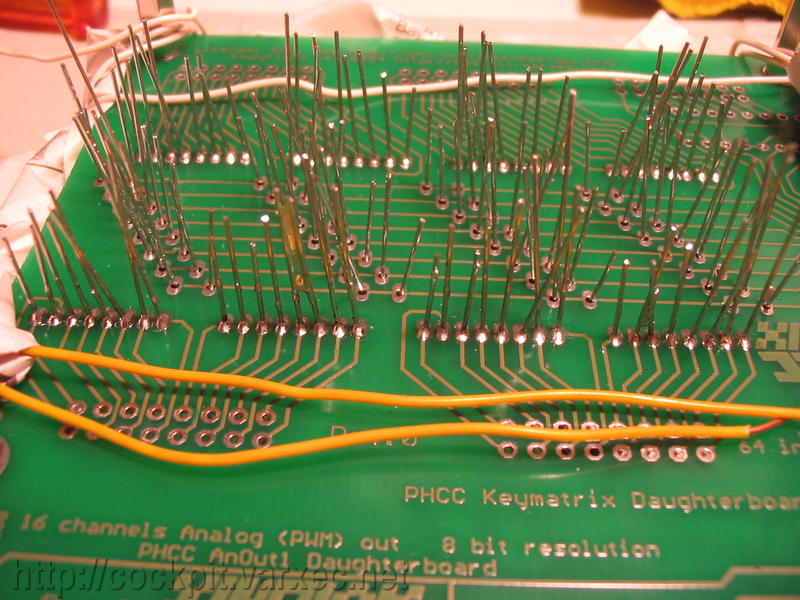
Now ready to solder all 64 diodes at once, without having to turn the board around. |
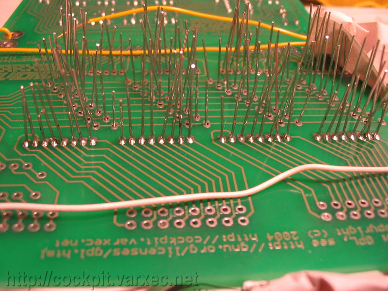 |
Its best to start with the outer rows. |
 |
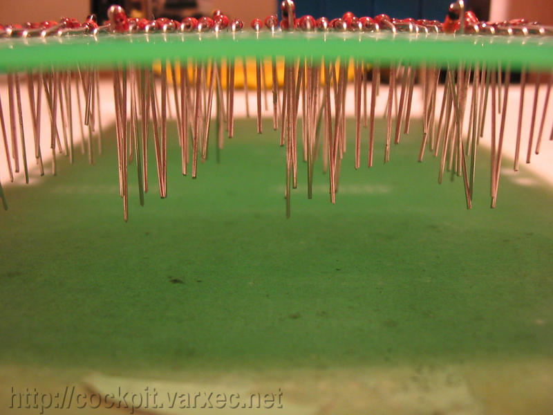
When both outer rows are soldered, |
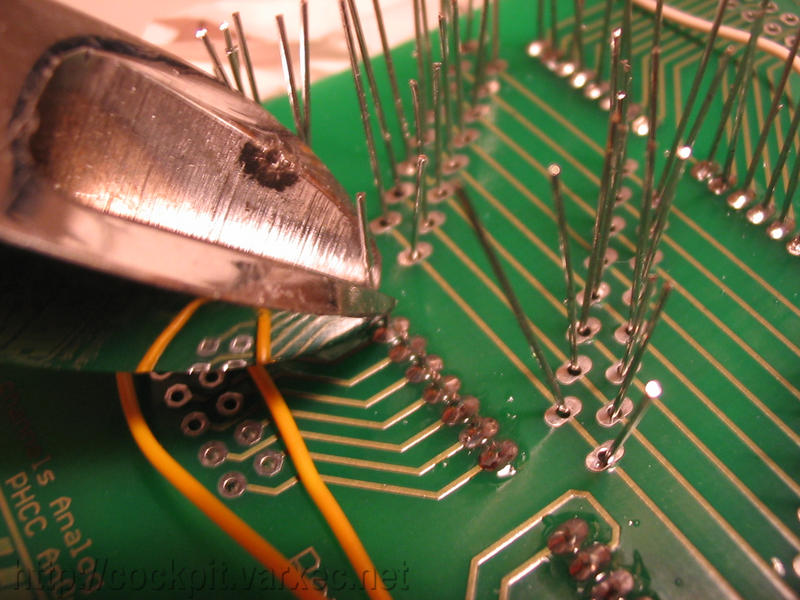 |
cut the excess lead length off with a wire cutter. |
 |
Now proceed to the inner leads. |
 |
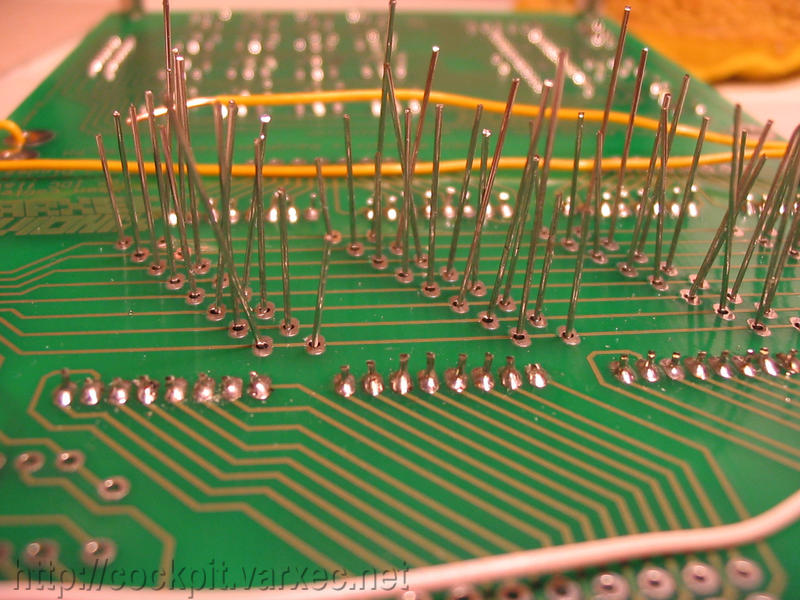
Once all of those are soldered as well, cut excess lead length. |
 |
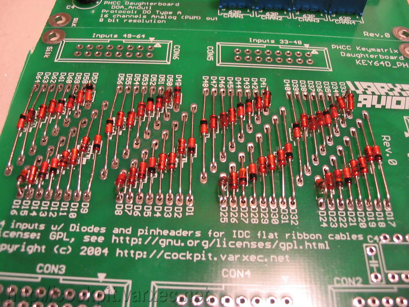
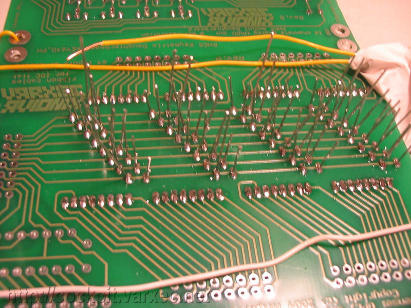
The newspaper can be removed and we can check if all diodes behaved and stayed in place. |
 |
Looks neat and clean. |
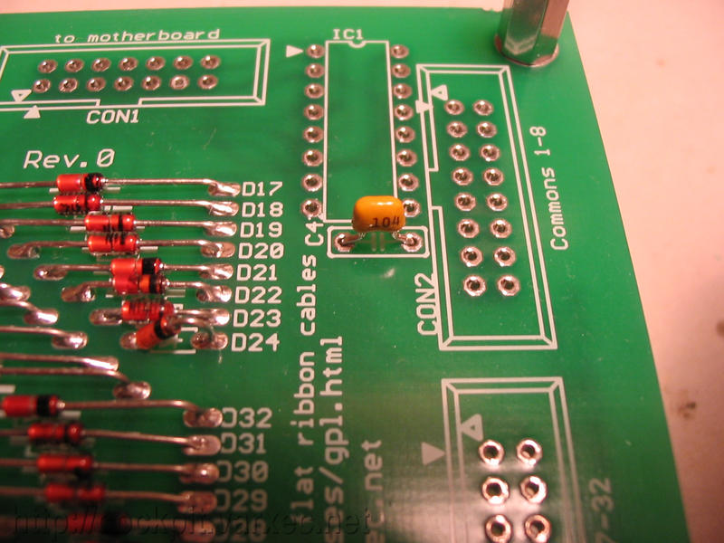 |
Next is C1, the ceramic blocking capacitor for IC1. Solder and cut. |
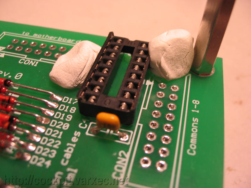 |
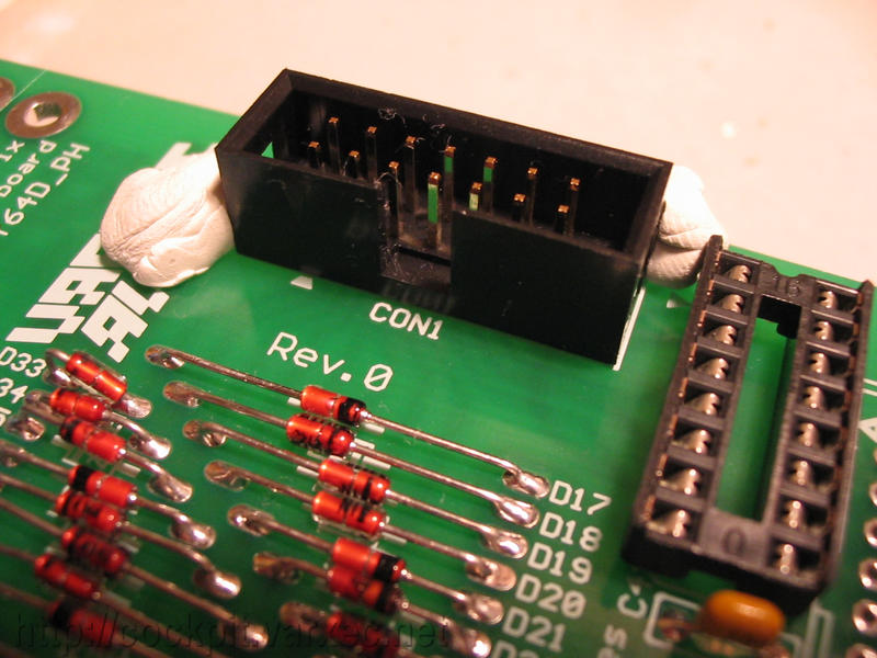
Now the IC1 socket. Using plasti-tak(R) (removable adhesive putty) I hold it in place to... |
 |
...solder. |
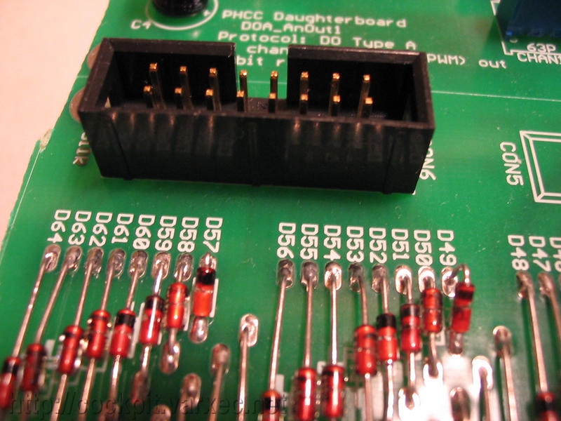 |
The last parts are the IDC pinheader connectors, CON1-CON6. |
 |
Again, these can be held in place before soldering using plasti-tak. |
 |
CON1 is a 14pin connector, CON2-CON6 are 16 pin connectors. |
 |
One problem thats only in Rev.0, Rev.0B has this fixed: CON3 reaches too far over the mounting hole, so I had to help myself with a sharp knife. |
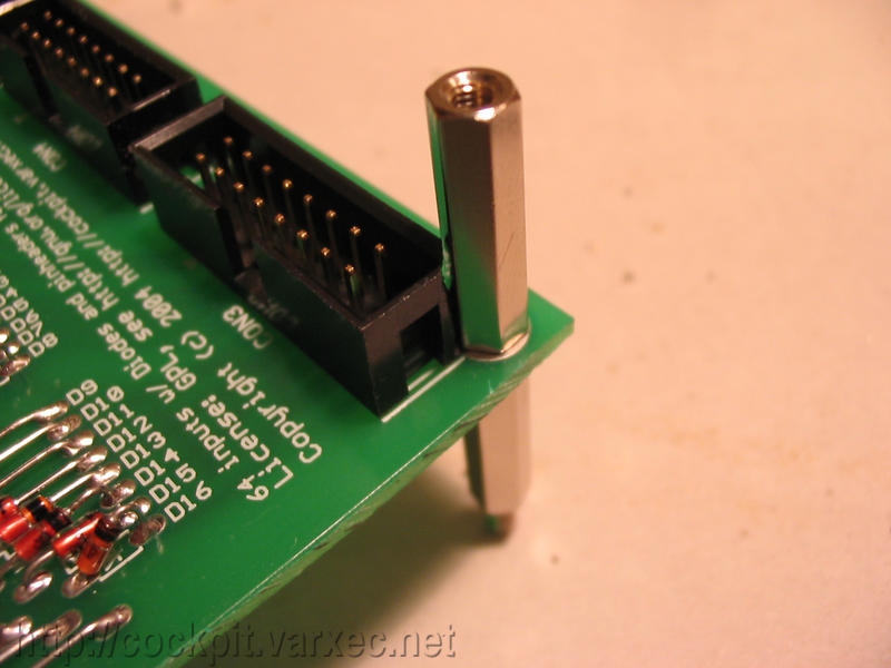 |
Ok, the cut was sufficient, the spacers fit. |
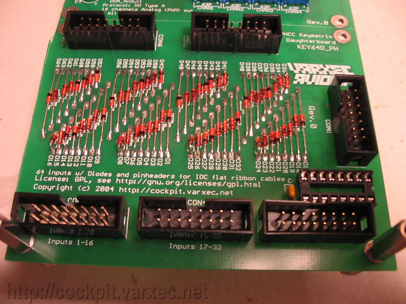 |
Everything in place, just one more thing to do ... |
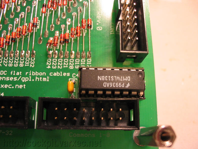 |
... adding IC1. |
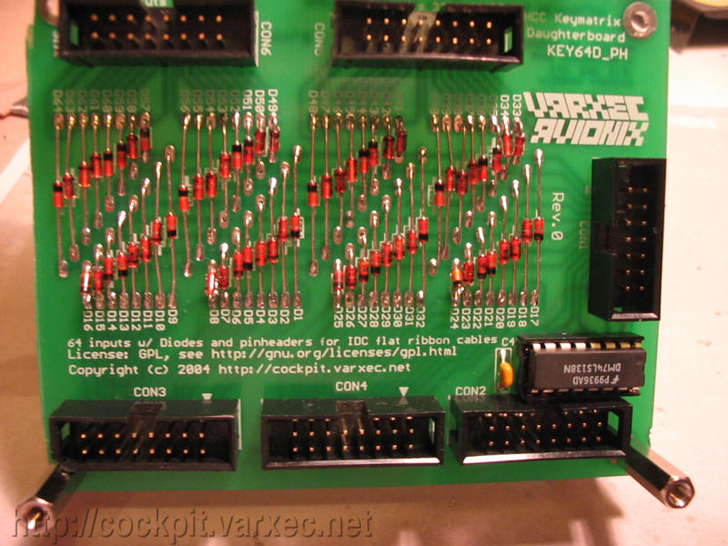 |
The finished board. |
Thats it :)