Assembling the PHCC Daughterboard "DOA_8SERVO"
Intro
The Servo Digital Out Type A Daughterboard is used to hook up standard RC-type servos.
It features 8 PWM servo outputs with individual calibration of both zero offset and gain (multiplier) that controls the movement range.
Variants
The resistor array RN1 (package: DIL-16) might not be easy to find in some areas. It is also possible to use 8 single resistors instead. In this case you could skip the step with the RN1 socket. Or, you could use a machined (turned) DIL-16 socket for the single resistors. Either just plug the resistors in the socket contacts or solder them to it.
How to connect stuff...
DOA bus to CON1, and up to eight servos to SERVO1-SERVO8
Make sure that your servo's pinout matches the pinout of this board: GND,+5V,PWM (counted from board edge inwards)
For further details see docs.
Assembly
First start with the smaller components and work your way up to the bigger ones like sockets and connectors. This helps at places where the bigger stuff might get in the way of soldering smaller parts.
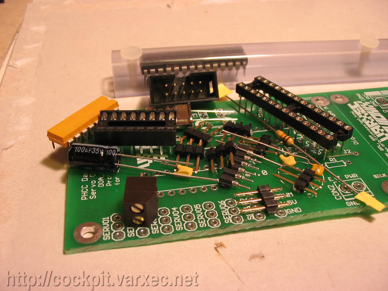 |
The bare board and all the needed parts. |
 |
If you don't have a double-sided board, start with the jumper wires J1 and J2. I didn't have to do this as I have a double-sided board. |
 |
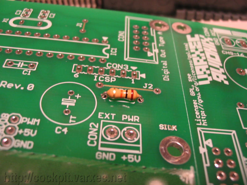
Bend the leads of resistor R1 to the appropriate size. Using a tool like this makes it easier but is not necessary. |
 |
Put in R1 in place. |
 |
Bend the leads so that the resistor won't fall out when the board ... |
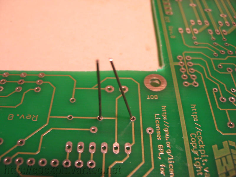 |
... is turned upside-down for soldering. Now solder. |
 |
Continue with C2 and C3, the capacitors for the crystal oscillator. Solder. |
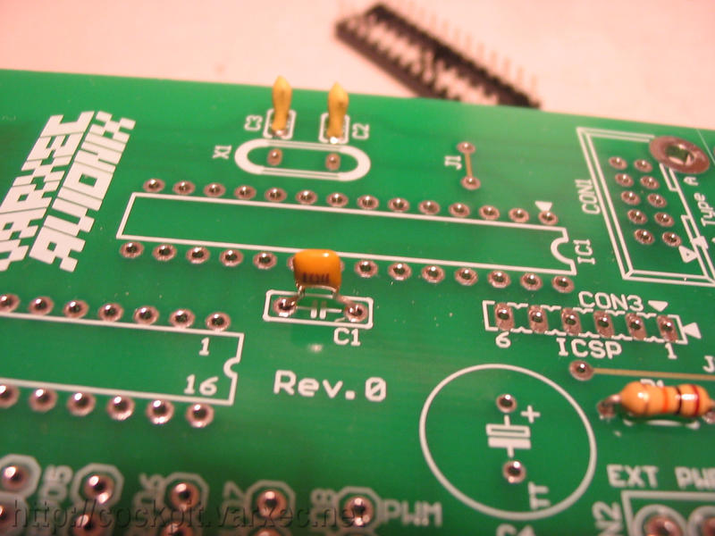 |
Then put in the blocking cap C1. |
 |
Solder. |
 |
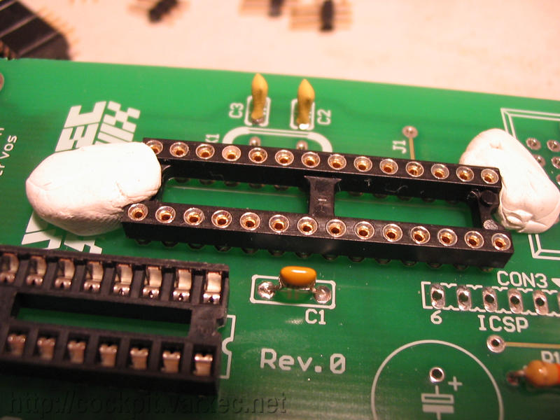
Now move to the socket for RN1. Using plasti-tak(R) (removable adhesive putty) I fixed the socket for soldering. |
 |
Solder. |
 |
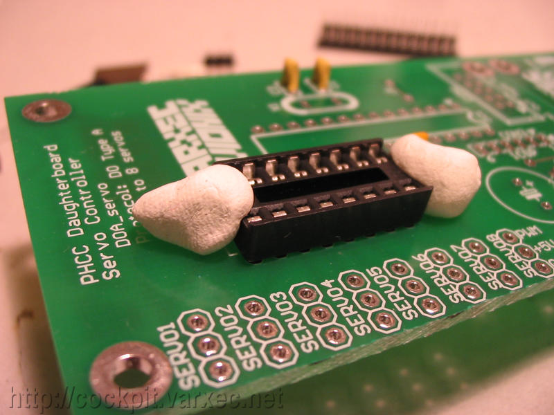
Next do the same with the socket for IC1. |
 |
IC1 socket when finished soldering. |
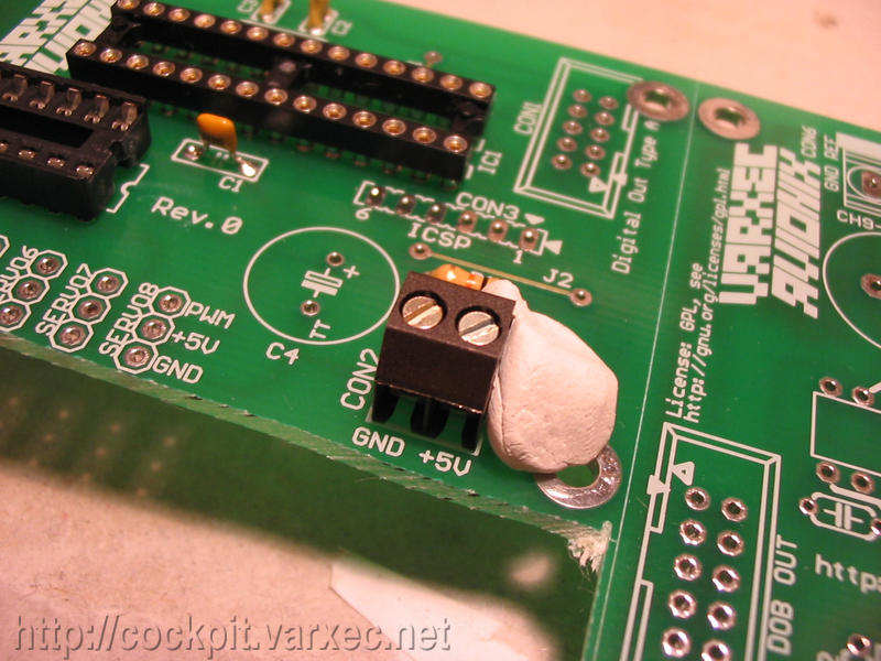 |
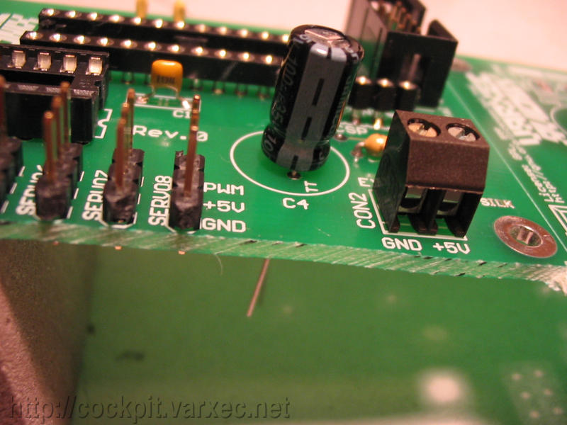
The external power screw clamp terminal CON2 comes now. Fixed with plasti-tak for soldering. |
 |
Solder. |
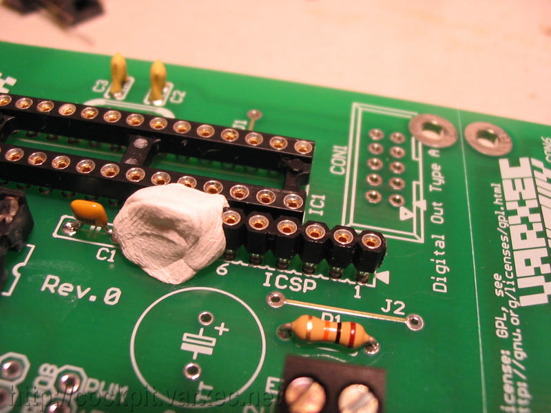 |
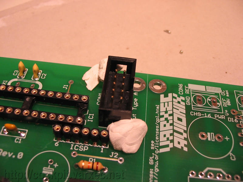
If you want ICSP(tm) (In Circuit Serial Programming), then add the ICSP socket, CON3. |
 |
Solder side view after soldering. |
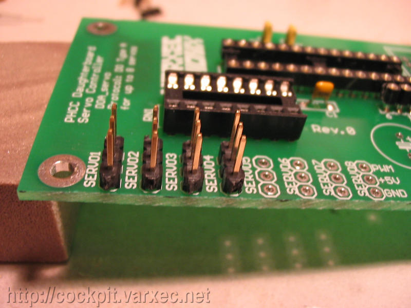 |
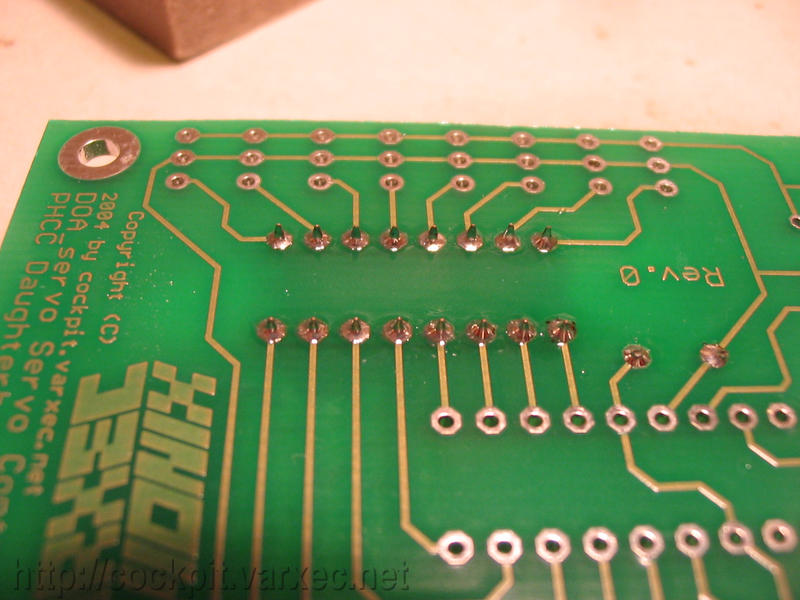
Now move on to the SERVO connectors. |
 |
I decided to do four at a time. Didn't want to use the plasti-tak method because it would heat up the stuff. |
 |
So I use an object I had at hand to set the connectors on like shown. |
 |
The brown 'block' is a kind of 'eraser' to clean the copper for making PCBs |
 |
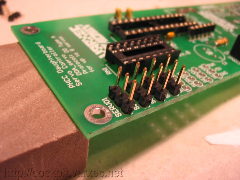
After soldering the first four, put in the second set of four and ... |
 |
... do the same. |
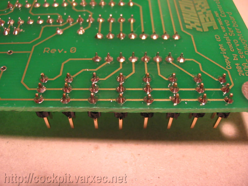 |
All eight soldered. |
 |
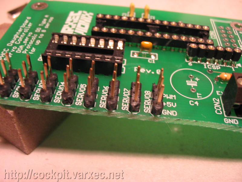
Next is CON1, the DOA connector. Solder. |
 |
Then comes C4, the electrolytic capacitor. |
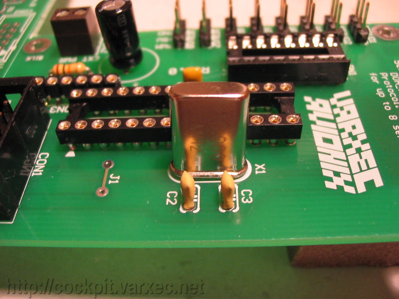 |
And the last part, X1, the crystal oscillator. |
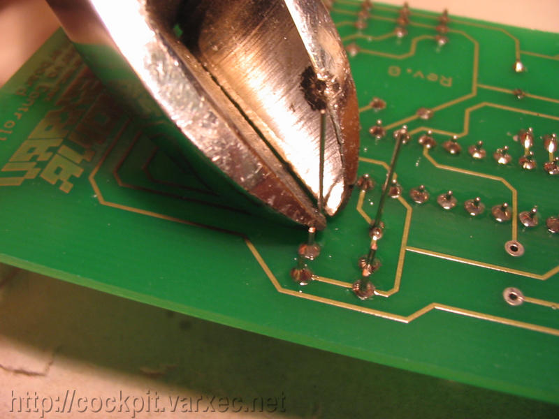 |
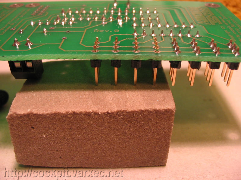
Cutting off the excess lead pieces. |
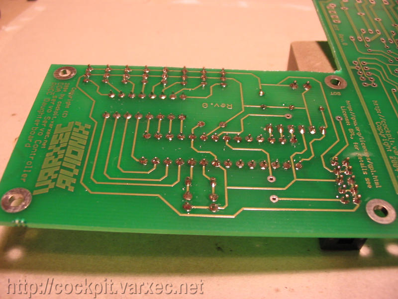 |
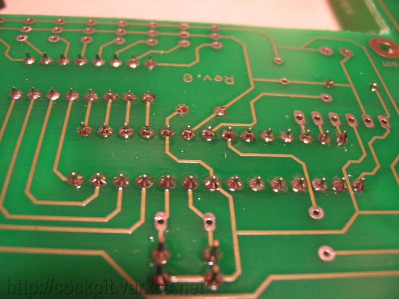
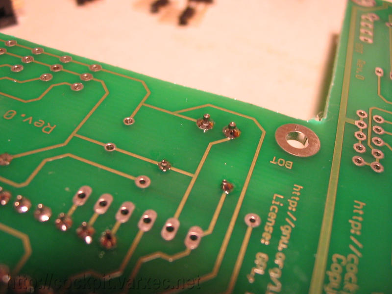
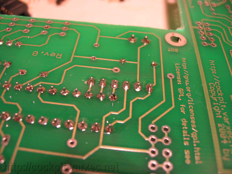
The solder side of the finished board. |
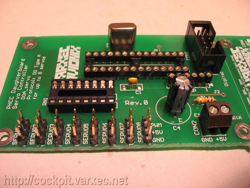 |
The finished board, parts side. |
Thats it :)