The PIC HomeCockpit Controller (PHCC) Motherboard
Description
The PHCC motherboard is the core component of the PHCC system. It connects to the computer via serial port (RS-232) or via USB.
A PIC18F452 microcontroller is used as the "heart" of PHCC. It is responsible for communicating with the PC via a simple protocol and it scans the Analog inputs as well as the keymatrix every few milliseconds.
The motherboard houses the following subsystems:
- 35 analog inputs (3 priority, 32 normal) in form of a pinheader with 3 terminals for each analog input
- 16 connectors for 16 keymatrix daughterboards (64 inputs per board). For IDC flat ribbon cables.
- a RS-232 serial port (for Null Modem cables) with level converter (MAX232)
- a socket for USB interface board
- an I2C port
- a connector for Output daughterboards of "Type A" (DOA) using a 2x5 pinheader for IDC flat ribbon cables.
- and a connector for output daughterboards of "Type B" (DOB) using a 2x5 pinheader for IDC flat ribbon cables.
Schematic and Layout
Current revision (Rev.4B) of the motherboard (Sept 28th 2004):
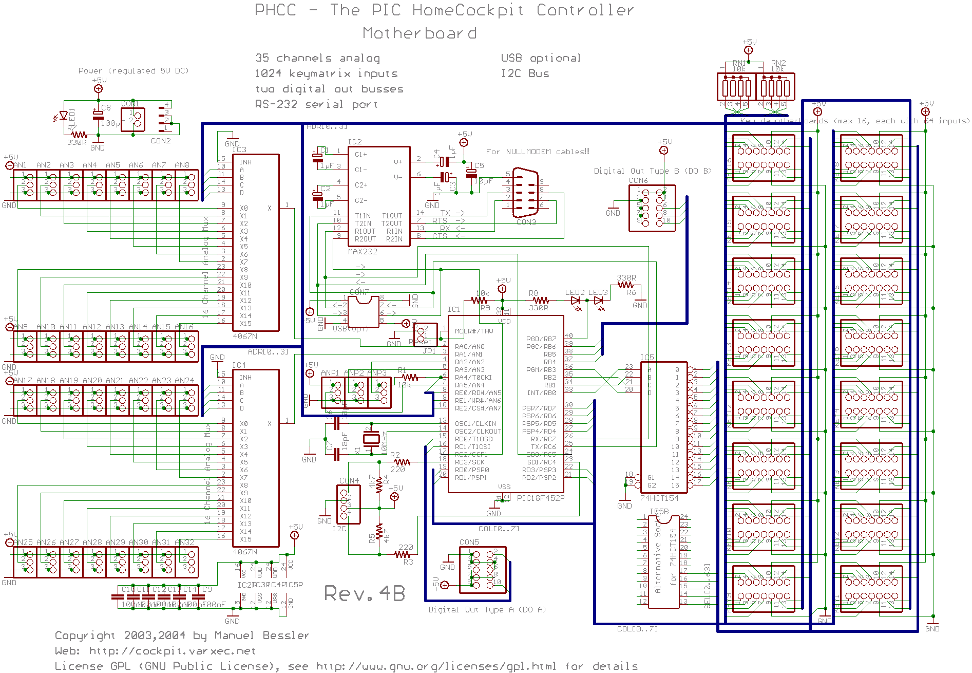 |
| Click to enlarge [99k, 1893x1310] |
 |
| Click to enlarge [86k, 1056x689] |
Revision 4 schematic and layout (Aug 16th 2004):
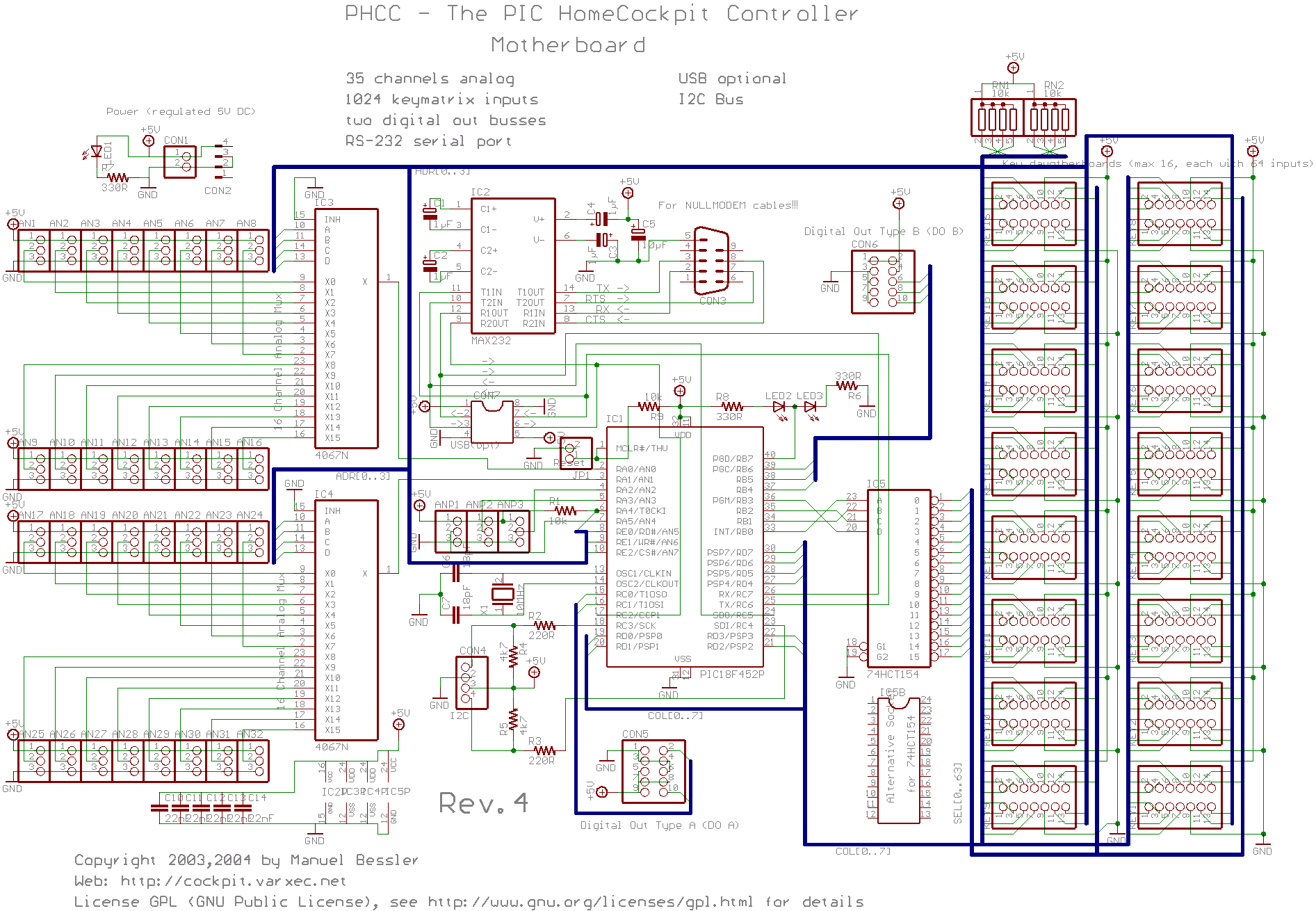 |
| Click to enlarge [99k, 1893x1310] |
 |
| Click to enlarge [78k, 1038x621] |
Assembly Instructions
work in progress, pictures to accompany descriptions soon.
- text only, Rev.4: Motherboard_Rev4_assembly_tutorial.txt
- text only, Rev.4B: Motherboard_Rev4b_assembly_tutorial.txt
Download
See download page
Note about Resistors: all resitors are standard kind, ie. 1/4W, carbon film, +/-10% (Its generally a good idea to get lots of 10k and 330R resistors. the 10k are for pullups, the 330R for LEDs)
Board Errata
The Rev.4 boards as sent to the boardhouse have a tiny mistake:
The numbering of the capacitors skips C8/9.
Changes between Revisions:
| Rev.4B | No functional changes. Added two Capacitors, one electrolytic for the incoming power supply, the other as a blocking cap, serving the second set of supply pins of the PIC. |
| Improved spacing between the KEY1-KEY16 connectors. | |
| Moved blocking caps of the 4067's to be nearer the supply pins. | |
| Narrowed the capacitor lead pitch of the MAX232's caps. | |
| Gave the resistors a bit more space. | |
| Put in markings for LED polarity. | |
| Standardized Mounting hole positions. | |
| Rev.4 | Had to change pins used for analog inputs since microcontroller allows only consecutive ADC pins to be used. You have to start with AN0. (Lesson learned: always read the datasheet first :-) |
| Added and beautified text and markings on component print (makes it look 'prettier'" :-) | |
| More space between pinheaders for DOA and DOB | |
| Fixed Debug LEDs. With Rev.3, only one of the two LEDs worked because of a thinking error. | |
| The 74HC/HCT154 is available in two formats, DIL24 and DIL24 narrow, now the board will accept both formats | |
| Reversed lines for lower nibble of PortB that control the 74HCT154. This makes the firmware easier. Old Rev.3 wiring is still supported in firmware via #ifdefs | |
| Rev.3 | aka. "The Prototype" |
| First finished and prototyped board. Had to manually correct the ANx inputs(see Rev.4) | |
| Rev.2 | These were never finished/fully routed boards. They were results of tests of either trials of how to run the traces or with different chips. |
| Rev.1 | |
| Rev.0 |
