This gallery shows how to build a nice replica for the pushbuttons used in the MCP (similar pushbuttons/switches are used on the overhead panels. Those are just a little bigger)
I modeled the switches after Korry's Chromalux 389 Series, which are (I believe) the actual switches used in the Rockwell Collins MCP for the 747-400.
For specs of the switches look here: http://www.korry.com/PDF/Korry_389.pdf
My switches are made up from 3 basic parts:
- the outer shell from square aluminum pipe
- the backplane with the switch
- the moving part with the LEDs and the Cap
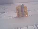
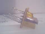
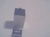
This picture shows the LED part.
Two sets of LEDs: two round ones for the legend (this will be the LNAV switch) and three rectangular ones for the "bar" in the lower half of the button.
Between the two sets of LEDs I soldered a piece of PCB as a "light shield".
side view
The vertical piece of PCB used as "light shield" was soldered on with the help of four pins from those standard pinheaders.
The round LEDs sit a little bit lower than the rectangle ones. This helps later for the lighting effects since the round LEDs are just the night backlight for the button legend. Ideally, those should be white LEDs.
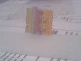
The rectangular LEDs almost span from the left to the right, just like the "bar" on the real ones.
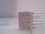
another angle
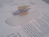
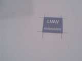
This is gonna be the cap for the button. Normal paper, laser printed, made with sketch. (If you want to know more about this program, go to http://www.freshmeat.net and search for sketch)
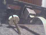
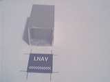
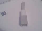
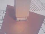
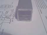
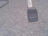
This piece of square Aluminum pipe is the outside shell for the switch.
Outside measurements: 2.0x2.0cm
Inside: 1.7x1.7cm
Length approx. 3.0cm
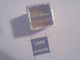
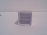
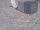
Test-fitting the LED board inside the Alu shell
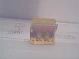
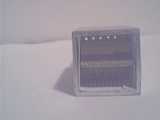
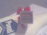
A potential candidate for a switch. (Actually a little too big)
This switch already has a diode built in, this simplyfies the keyboard matrix.
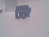
The switches outside size is about the same as the alu pipe's.
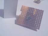

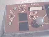
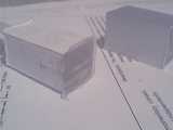
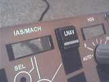
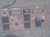
The MCP panel
Testing the sizes
fits perfectly
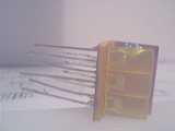
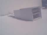
A ribbon cable attached to the LED board. This has each of the 5 diode's pins on a seperate wire for now.
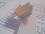
Also notice the folded paper looking out the back part. This plays an important role soon.
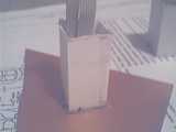
Whats gonna be the front of the switch seen here. Again notice the paper thats folded to fit exactly in the alu pipe
a little closer
from the side
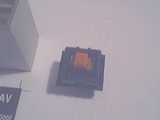
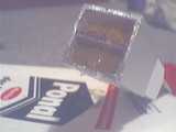
Now I've added the hot glue to the front part, ie. above the LED board, covering the LEDs.
Its probably not easy to see since the glue is still hot here and thus is pretty much transparent.
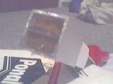
One note about the depth/distance: I've set the LED board such that the rectangular LEDs tops are flush with the front of the Alu piece. That way I get most brightness out of those LEDs for the "bar"
Now I'd like to have a nice flat front where I can glue the cap I printed onto. To achieve this I set the cooling glue against this piece of unused PCB. The copper allows easy detaching of the glue later on.
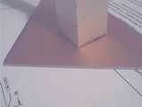
Carefully lifting the alu piece up, makeing sure the glue does not hang onto it.
The paper clearly seen here acts as an easy way to keep the glue from getting onto the alu and it also acts as a "spacer" that lets the inner part slide inside the alu piece.
After carefully pulling off the PCB, we've got a nice front for our switch.
without the alu.
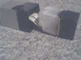
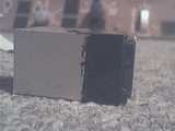
After painting the front half black.
The inner part is also painted black, except for the face that'll get the cap.
As you can see here, the back part was also "hot-glued into shape". Basically same procedure as with the part the covers the LEDs.
Also don't forget to rub off the paper (soak it in water first).
from the back.
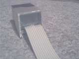
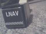
Finally the cap glued on.
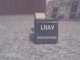
side view
front closeup
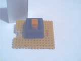
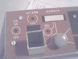
Installing the switch to its place in the MCP panel.
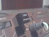
like this
Ok, one down, twelve to go............
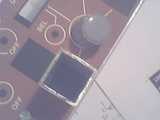
The back of the MCP panel