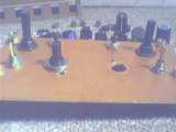
This gallery depicts part of the assembly of our EFIS panel.
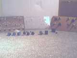
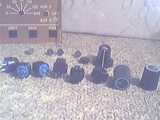
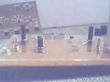
Some parts at the front, then the 3 panel parts:
From left to right: the printed panel, plexi backer, and the mounting plate.
Closeup of the printed panel. This actually consists of 3 parts: (front to back) a thin tranparent adhesive, normal white paper printed partly brown, and a inkjet or laser transparency printed black to block light (see other panel galleries for pics)
plexi backer (ours is actually not plexiglass, but something similar which is easier to work with)
and the back-plate. This is actually a double side copper PCB. Sturdier and it doesn't brake as easy as plexiglass et al.
some of the parts.
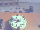
the PCB back-plate/mounting-plate
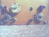
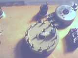
again the back of the PCB, with one rotary not mounted yet
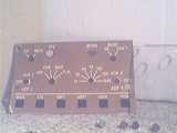
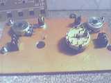
front side of PCB
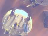
an interesting experiment: since both the ND Range and the ND Mode selectors have pushbuttons integrated, I tried to come up with a simple and cheap solution.
I drilled a 5mm hole into the white bottom part of the rotary. Now, the axis as a vertical play of about 1mm which can be used in conjunction with a microswitch...
... I got the small green microswitches really cheap (1.50 EUR for a bag of 100 :-)
And the size is just right for this. It only needs to be glued onto the rotary.
... just soldering wires the the contacts of the microswitch is not that easy.

different angle

This should show it nicely
and again another angle
putting the whole thing together... plexi backer
again
printed panel laid on top.
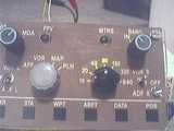
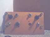
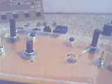
the whole thing screwed together and adding some knobs
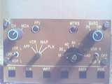
I know, the knobs don't match, but better than nothing right now :)
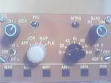
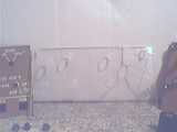
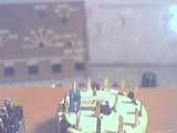
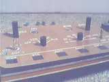
backlighting test: 4 yellow 3mm LEDs dangling between the plexi and the mounting plate.

even visible in daylight.