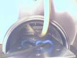
This gallery shows how the steel wire for the aileron/yoke linkage gets attached to the pulleys.
It shows all the parts that we use in the upper part of the control column where the yoke is attached to.
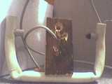
This first picture was taken before dismantling
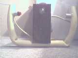
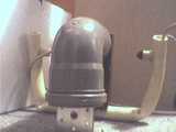
from the side
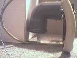
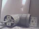
the angled part is a 85 degree PVC water pipe angle piece.
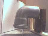
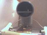
from the back. As you can see, this is the captains yoke, since the AP disconnect pushbutton is on the lefthand side (when seen from the front, of course)
with the yoke flat on ground: looking inside the pipe piece
angular piece turned aside
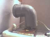
with the yoke removed: the two metal pieces (the plus-shaped upper one and the one looking out the bottom) are what's called "Lochblech" in German, sheet metal with holes which you can get at any home improvement store around here in many forms and sizes.
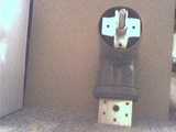
the back of the yoke. doesn't really look nice...
I tried to drill some holes halfway into the wood piece in a half circle kinda shape for the cable (trim, AP disconnect, PTT) to run in when the yoke is turned.
the angular piece, flat on the floor. the yoke axis is a M10 threaded rod
here you can see the plus-shaped metal piece is held in place by one screw on the bottom (and, not visible in this pic, another one on the top
here the screw on top can be seen as well as another one (lower part of the picture) that holds the other piece of metal
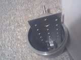
looking inside the bottom part...
closeup of the yoke axis and the plus-shaped metal piece (cut with an angle grinder [german=Winkelschleifer/Flex])
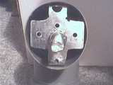
the plus-shaped part taken out
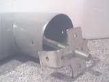
looking inside from the front, you can see the pulley where the steel wire linkage will run over
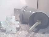
from the bottom, the pulley again
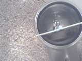
how the metal piece is attached from the inside
from the front with the threaded rod with the pulley taken out
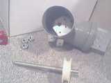
the pieces (without the nuts) as they were assembled inside the angular pipe piece
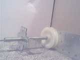
from another angle.
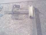
yet another angle. this should give you an idea how the long metal piece is formed
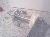
the upper end of the long metal piece is formed like a hook.
there's a hole on the end of the hook where the metal piece is attached to the PVC as seen in previous pictures
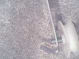
adding the steel wires
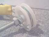
again
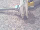
the long piece of metal put in place again, now adding the pulley with the steel wires attached
Note: the pulley sits VERY tight on the treaded rod. moving it by hand is nearly impossible.
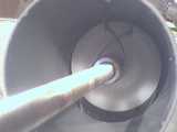
another angle
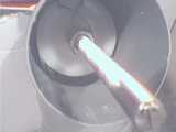
screwing the yoke back on the axis
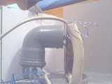
from the front.
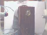
the bottom of the angular piece, with the steel wires and the cable for the buttons coming out
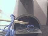
better lighting
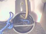
and a closup.
