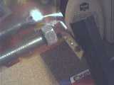
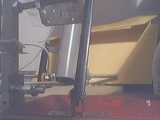
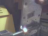
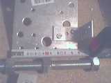
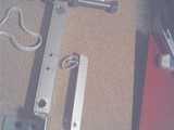
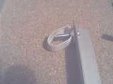
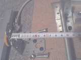
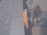
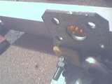
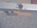
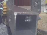
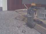
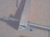
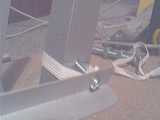
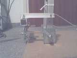
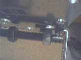
First of all, the toe brake mechanism I'm experimenting with.
its basically a L-bracket mounted to the pedal plate. It is important that the braket is mounted such that the pivot point where the vertical rod is connected to describes a circle when the breke is activated. Otherwise that mechanism will lock either when braking or when moving the rudder (probably both)
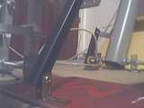
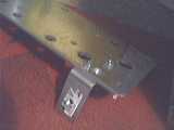
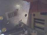
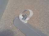
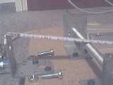
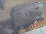
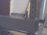
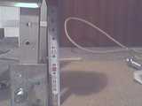
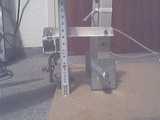
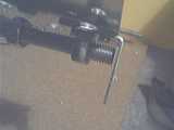
the lower part of my test mechanism for the toe brake. Later, the black rod will have to be able to move up and down during braking.
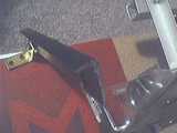
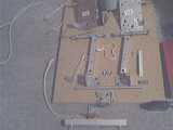
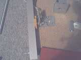
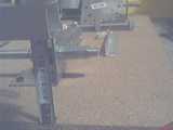
the thing flat on the floor
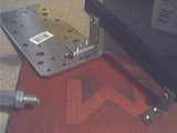
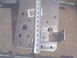
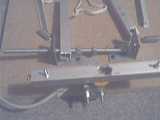
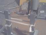
brake/rudder pedal plate and L-bracket of the brake mechanism
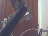
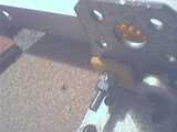
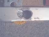
maybe this pic makes it clearer: the hole on the bracket thru which the vertical rod is connected must always have the same distance from the center of the threaded rod (rudder pedal), otherwise its not gonna work right !
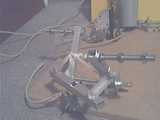
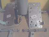
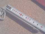
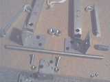
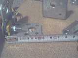
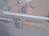
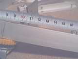
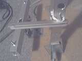
This starts a sequence of how I built my rudder pedals. Here is an overview of all parts used. I also put a meter next to some parts in some pics so you can see the sizes.
(And yes, I took the thing apart for this gallery :-)
Lets start with the pedal plates and the threaded rods onto which they'll be attached.
Its a M12 threaded rod. M10 would also work fine.
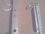
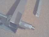
The vertical rudder part and the links to the crossbar.
Its a 2x2cm square Alu pipe
the link to the crossbar
Thats a M3 screw and nut holding the rubber band.
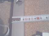
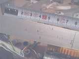
Sorry for the blurry image, it should read about 11cm total length for the link.
And about 9cm between the holes
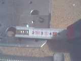
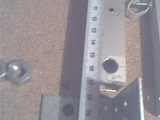
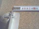
Distance from the upper 12mm hole to the 3mm hole for the link is 7.1cm (disregard the rightmost hole, thats from an older, longer version)
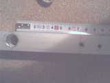
Its a total of 14.2cm between the upper 12mm hole and the lower 10mm hole and pivot point and
6.8-6.9cm between the pivot hole and the 3mm hole for the link
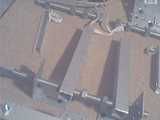
The 3 brackets mounted to the base board
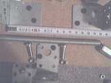
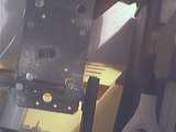
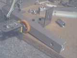
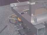
Now a couple of pics with closups of the crossbar and where it connects to the pot
The yellow piece is PVC, better would be some Delrin or other plastic washer.
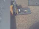
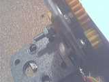
there are 2 metal washers that sandwich around the L-bracket onto which the whole thing is mounted
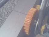

The yellow gear wheel has a crack because I tightened the nuts too much :( But it still works. :-)
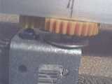
two screws, one as the pivot point, the other prevents the gear wheel from moving relative to the crossbar.
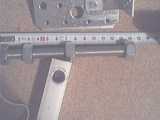
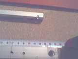
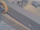
its about 20.5 cm long total, same material as the vertical rudder arms.
and about 8.0-8.2 cm from the screw to the center/pivot
same here. (actually I made a little mistake here and this side is nearly 0.5cm further out from the pivot
seen here is the lock screw through the gear wheel.
Starting to reassemble, step by step.
This actually needs some plastic washers (right and left of the vertical rudder arm)
the crossbar. about 9cm above the base board is where the link will sit.
sliding on the link
putting the M3 screw in its hole. It will NOT have any kind of nut put on through the vertical arm, the rubber band will hold it, while still being flexible enough
But wait... don't push it in yet, we need another measurement :)
Its about 9.5 cm from the base board to the hole for the link
push the link on the screw on the crossbar
and fasten with a nut (but not too tight, it'll have to be able to move a tiny bit at larger rudder deflections.
the more horizontal the link is when the rudder is in neutral, the better
the link sits about 9cm above the base board
starting to attach the M12 rods
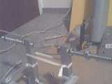
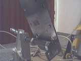
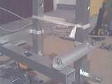
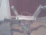
trying to give you a picture of how I imagine the toe brake mechanism (the pedal plate is not attached yet, just held in place for the pictures)
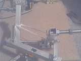
max rudder throw in one direction
and the other
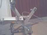
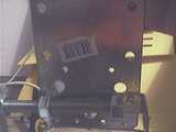
the same again from the top/front