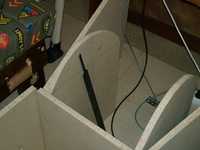
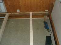
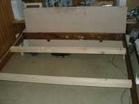
new frame that the cockpit will sit on, this is the forward left corner
the dark kind of wood builds up the outside frame (4 beams: right,left,front,back)
the bright kind of wood is used for the legs and the inside right-left stabilizer beams.
the legs lift the cockpit floor up by about 45cm :-)
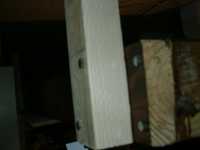
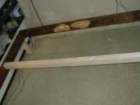
closeup (upside-down) of one leg mount
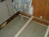
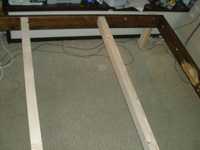
here are the beams used for the inside stabilization
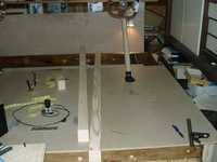
now they are mounted in place
the back(-cockpit part) of the frame
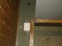
other side of the back
right side
the whole thing
control columns, pedestal mounted, captains chair put in place
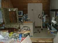
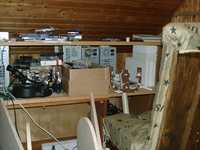
major changes always incur chaos
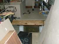
back of cockpit, stairs will go in front of the speaker in the picture
although its not too good of a picture, you can see how high up the cockpit floor is
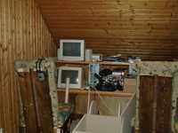
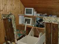
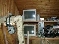
both chairs set up, with the old shelf for the monitors still there
different angle
yet another angle
from behind the captains chair
early pedestal, and the beginnings of the throttle unit.
inside the throttle unit you can see what will become a throttle lever